


Products
Contact Us
Company: Shanghai Skyline International Co., Limited.
Address: Room 1215,No 333 Jin Xiang Road, Pu Dong District, Shanghai,China Zip Code: 201206
Cell/Whatsup/Viber: 0086-1363-6587-123
Tel: 0086-21-60513390
Fax: 0086-21-51062003
E-mail:diamond.chang@hotmail.com sales@motor-cycle-part.org
Contact person: Diamond Chang
Technical
Rebuild Fuel Pump 393088
Time:2016-03-24 17:55 Author:admin Click:Times
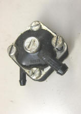 |
Rebuilding the old OMC Square Fuel Pump
|
 |
The illustrations below are copied off OMC's fuel pump repair kit instructions #393088
but will also be applicable to the Sierra or NAPA #18-7823 kit
The instructions here are not mine, but OMC's
This same basic fuel pump was used on many motors from made from 1959 thru about 1987
for 2.5 hp up to 40 hp
NOTE-- THESE ARE A PITA TO GET RIGHT THE FIRST TIME & MAYBE EVEN THE SECOND TIME AROUND, SO IF OR WHEN YOU DECIDE TO GO INSIDE YOUR PUMP BE VERY OBSERVANT.
THE NUMBER ONE THING TO DO IS TO ONLY REMOVE THE TWO HORIZONTAL SCREWS WHEN REMOVING THIS FUEL PUMP FROM THE MOTOR. REMOVING THE OTHER TWO ALLOWS THE WHOLE SHEBANG TO COME APART & YOU WILL NOT THEN KNOW WHERE THOSE SMALL INTERNAL PARTS CAME FROM.
NOTE -- These 8 illustrations are from scanned pages from the original repair kit.
 |
|||||||||||||||||||||||||||||||||||||||
|
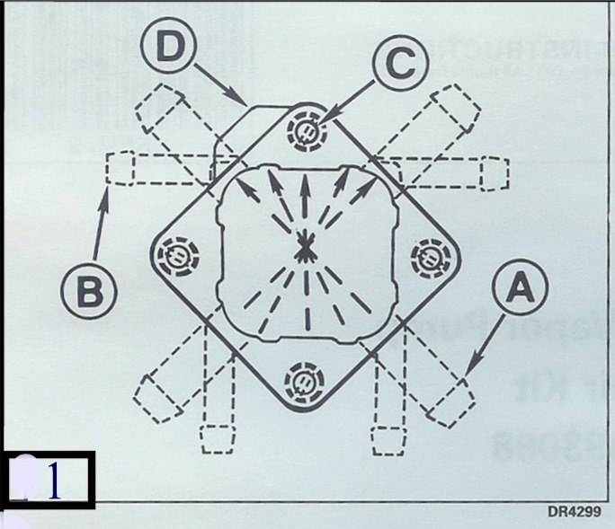
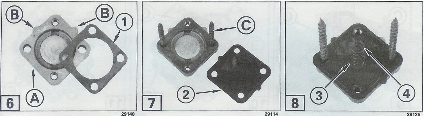
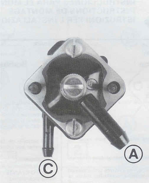
Preface Call out NUMBERS (1), (2), etc. in the text and illustrations refer ONLY to the specific items in the Contents of the Kit illustrations and list. Call out LETTERS (A), (B), etc. are used over & over - on different items in other illustrations. Before disassembly, draw out arrows on your unit indicating UP when the unit is mounted on the motor. Also draw in the position of the fuel pump inlet fitting (A), the outlet fitting (B) and the assembly screws (C), relative to the wide valve body tab (D). Note some early units do not have this moulded in body tab. This sketch will later be used to reassemble the pump correctly. |
|||||||||||||||||||||||||||||||||||||||
 |
|||||||||||||||||||||||||||||||||||||||
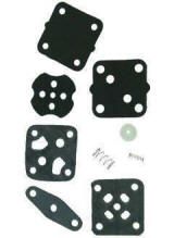
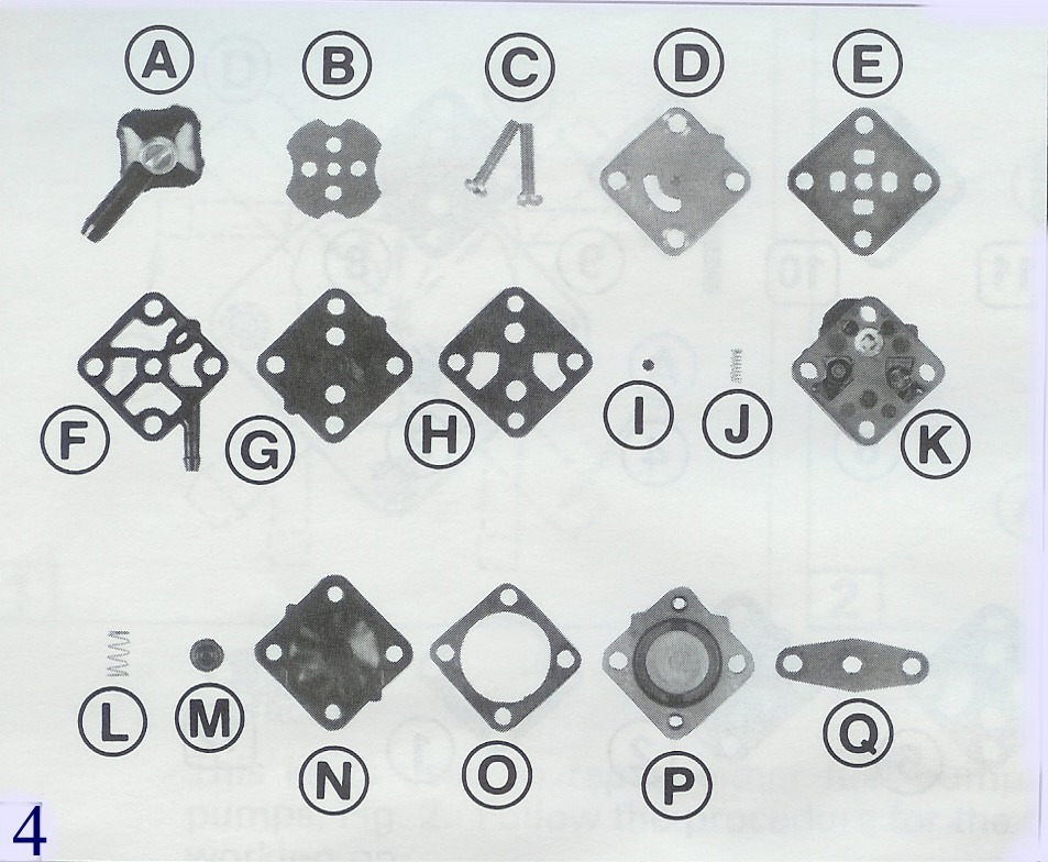
Contents of the kit
Clean the pump exterior and work on a clean bench to avoid pump malfunctions caused by dirt. A word of caution, use a large clean paper or cardboard as some of these springs are small & tend to disappear. |
|||||||||||||||||||||||||||||||||||||||
|
|||||||||||||||||||||||||||||||||||||||
|
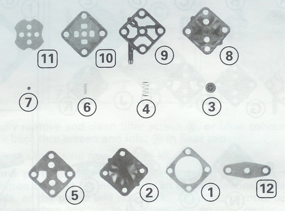
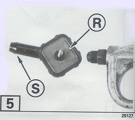
Fuel Pump Servicing (4) remove and place each piece on your clean bench, as it was positioned on your pump. Some may be slightly different than in this illustration. (A) Filter Cap Assembly (J) Air-dome Spring (5) Carefully remove the filter screen (R) or blow solvent and air back thru screen and inlet (S) in filter cap. |
|||||||||||||||||||||||||||||||||||||||
 |
|||||||||||||||||||||||||||||||||||||||
|
NOTE -- Some parts in this kit must be installed in an exact position or must be installed in an exact relationship to other parts, or the pump will not work. Other parts must be installed in a certain position to fit hoses, etc. on your motor. (7) Place the pump diaphragm (2) on the base gasket. The assembly will be easier if two screws (C) or nails, are inserted up thru the pump mounting holes. (8) Place the diaphragm support (3) in the center of the diaphragm spring (4) on the diaphragm support. |
|||||||||||||||||||||||||||||||||||||||
 |
|||||||||||||||||||||||||||||||||||||||
|
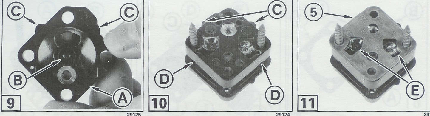
(9) (10) Place the valve housing (A) on the diaphragm spring, with the spring fitting into the recess (B). The two valve housing tabs (C) must be UP (as they are on your motor) and the two drain holes (D) must be DOWN. (11) Place the valve housing gasket (5) on the valve housing with the gasket cutouts (E) aligned with the air-dome spring cavities. The position of the outlet ((B) Fig. 1) on your motor determines the location of the air dome spring (6) and the air-dome support (7) on the valve housing. |
|||||||||||||||||||||||||||||||||||||||
 |
|||||||||||||||||||||||||||||||||||||||
|
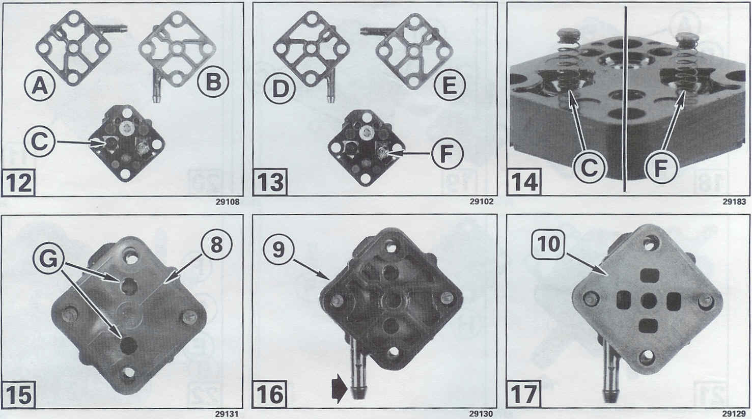
(12) If the outlet housing was in position (A) or (B), the spring and the support must be in cavity (C) (13) if the outlet housing was in position (D) or (E), the spring and support must be in cavity (F). (14) Install the air-dome spring(6) and the air-dome support (7) in the correct position (C) or (F) (16) Install the outlet housing (9) where the original outlet housing (8) Fig. 1 was positioned, which is the position used to determine the spring and support location. |
|||||||||||||||||||||||||||||||||||||||
 |
|||||||||||||||||||||||||||||||||||||||
|
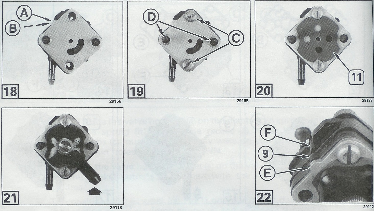
(18) Reinstall the cover with the stamped letter "U" to the outside. Turn the cover so the tab on the cover (A) is next to the tab (B) ON YOUR HOUSING. These two tabs must be together or the pump will not work. (19) Check to see that the main diaphragm spring and theair-dome spring have not moved out of position. Reinstall the assembly screws (C) or (D) ( (C) in Fig. 1). (20) Install the filter gasket (11) with the smaller cutouts next to the assembly screws. (21) Reinstall the filter cap assembly in the original position (A) in Fig. 1. (22) Check that the tab (E) on the cover is in line with the tab on the outlet housing (9), and is in line with one of the tabs (F) on the valve housing. |
|||||||||||||||||||||||||||||||||||||||
 |
|||||||||||||||||||||||||||||||||||||||
|
Fuel Pump Test (23) You SHOULD be able to blow thru the pump by blowing into inlet (A). You should NOT be able to blow thru the pump by blowing into outlet (C). If the pump does not pass this test, disassemble pump and check the parts that must be in an exact position or must be in an exact relationship to other parts. After pump is installed, squeeze primer bulb until firm. Check pump and connections for leaks. Correct any leaks before operating motor. |
| This is not a factory photo, but shows the positions of the related parts |
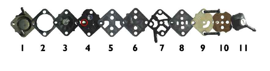 |
These repair kits are not listed for any pre 1981 fuel pumps even though they are the same. The difference is that the later bodies have projections cast in the metal that matches the tabs on the diaphragms. This is to ensure the parts go back together right. You can do the same by making a felt marker stripe across the metal on one side before you take it apart to ensure you have it back together right.
You can see from the above factory information that IF you need to change the location of the outlet to clear say the terminal block of a electric start motor, that it is possible, BUT follow the placement of the parts.
The reason I mention at the top of this article that it is a PITA to get it back together right the first time, is that while holding everything together AND trying to keep the springs and their supports in position (the small spring tends to flop over on final reassembly). TEST THE REBUILT PUMP AS IN #23. To keep the springs and their supports in position, you may consider placing a dab of Vaseline on the both the spring's tail and the head of the support just prior to reassembly. This can hold them in position long enough to get the other parts aligned and yet not hinder the final operation of the fuel pump.
Now for those of you who loose that #7 (Air Dome Support), or plunger to many of us, here are the dimensions. This drawing is small enough that you may not be able to distinguish the radius corners on the large diameter of the outer head. However possibly a shortened 1/8" Pop-Rivet could be improvised to function.
Sierra Kit #18-7823 has all the internals including the small springs and air dome support.
| OMC square fuel pump, air dome support dimensions |
 |
(editor:admin)
Previous:How to Choose Motorcycle Rims or Wheels Next:None